Date: Sun May 30, 1999 12:34 pm
On the propeller shaft, we replaced the cutless bearing while we were at it, put in a new dry/dripless stuffing box, and more recently went to a Max Prop 16-10 for better backing power and lower resistance under sail
Date: Tue Feb 27, 2001 12:32 pm
Dripless Shaft Seal (15Nov00): PYI non-flow seems far the best for non-cats sailboats,as it is totally passive and self-cooling, as long as the bubble is expelled on lauching to make sure water fills the insides. A Tide Marine Strong was fitted instead during my upgrading, and I discovered too late its cooling circuit tied to the engine cooling. Sure enough, it failed after a few months at sea, and another time a couple of months later despite using reinforced fuel hose: the piping twists or kinks and breaks. This could apply to forced cooled PYI, although I don't know the design specifics.
Date: Mon Mar 5, 2001 7:29 pm
Has anyone replaced their cutlass bearing and/or stuffing tube? Is the tube locked in with set screws or can it just be knocked out? I'm thinking of installing a dripless (lasdrop) or equivalent.
Date: Mon Mar 5, 2001 8:27 pm
I replaced mine 2 years ago. There were 3 small set screws covered with gelcoat. I was very easy to drive the thing out with a big socket and a long bolt and washer. However it should be noted that I had removed the fuel tank before attempting this, so there was lots of room. Otherwise, you might need a couple leprechauns to access it. I put on a dripless packing
(PSS). Now there is nothing but dust, and a few tools, in the bilge.
Date: Tue Mar 6, 2001 9:27 am
I was unfortunately not present when my wrecked Strong seal (from Tides Marine) was replaced by a PSS from PYI (passive cooling, no forced cooling) which had been my first choice. I found since that the unforced cooling PSS is put on Swans as original factory equipment, and the Swan charter fleet manager has never had a problem. It is however most important, at each launching, to squeeze the seal aftward to expel the "buble" that might restrain natural cooling.
The cutlass bearing was dismounted along with the stuffing tube, and was half corroded, so we replaced that too. The technician of Bobby's Marina (St.Maarten) was no leprechaun but a tall thin islander who told me it was tough. Which is the first reason for replacing the original stuffing box by a no-maintenance, dripless Permanent Shaft Seal (PSS).
But make sure it is of the unforced cooling, totally passive type (PYI's PSS has the only type I know, and good enough for sailboats except may be fast cats, do not use the forced cooling PSS, probably necessary for fast motor boats and cats). Besides requiring a tap on the engine raw water cooling, forced cooling adds another potential problem, which I encountered twice (kinks or even breaks in the hose, even the heavy fuel reinforced hose I installed in Porto Santo) with leaks in the bilge and reduced or no cooling of the seal, twice before the shaft disconnected from the transmission box and wrecked the seal.
Note I was saved from a shaft loss and a huge flooding leak by the shaft anode screwed inside on the shaft, not that it helps corrosion in the bilge which should not fill that high, but it stops the shaft from pulling out of the stern tube. That is a cheap but most important insurance.
Date: Tue Mar 6, 2001 6:42 pm
I have replaced both the rudder post and propeller cutless. The propeller cutless had 3 set screws holding it in place. They were easily acessable from the outside (my boat was hauled at the time) for removal. Once the propeller shaft was removed I took a socket that fit the inside diameter of
the tube and drove it out from the inside out. I supose you could drive it in toward the bildge if you had a method of catching it.
The rudder post cutless was a little different. There was also 3 set screws holding it in place but were nowhere to be found. Removal of the cutless was from the cockpit out. Method was the same. I didn't realize about the set screws until the cutless was removed.
Can' tell you anything about a dripless shaft seal. I went back to the original packing configuration.
Date: Wed Mar 7, 2001 9:03 am
We replace our bearing every 4 years while hauling for antifouling. Our serial is 129 and ketch rig.
The bearing on the outside of hull has a bullet shaped dome which we cut with a hacksaw 1/2" back from the trailing edge all the way around. Then take 2 hacksaw blades and cut just enough for a screw driver blade to get a grip through the brass on each side and top. Then cut away enough of the glass on the sides of the bullet to find the set screws, back these out, then take two screw drivers and using leverage in the slots you cut pry the bearing out aft. Note, use two screwdrivers at the same time, then cut two more slots, and pry again, cut two more slots and pry again.
You gain about 1" for each set of cuts and before you know it, the bearing will slide right off. You must remove the propeller first of course.
Date: Sun Aug 5, 2001 3:02 pm
I've reread your system of replacing your cutlass bearing and have a few q's. I cant seem to find the set screws! Are they in the cone or the deadwood area parallel to the shaft log? Also, do you actually remove the cone section 1/2" fwd of the trailing edge of the existing bearing? This sounds like what works but want clarification before I start cutting into the old girl...
Date: Sun Aug 5, 2001 4:17 pm
I have just changed the cutlass bearing as I replaced a damaged shaft (full report later on shaft, coupling and shift/gas handle) and the two setting screws are centered on each side of the cone, deeply inset, about 1-2" from the cone end if I remember (boat is back in the water). This was second event of disconnection from transmission box in 18 months (possibly linked to strong backing power of my 3 year-old MAXPROP...), so I made drastic changes!
Date: Mon Aug 6, 2001 1:25 pm
Facing the starboard side of the boat, and looking at the shaft/propeller from that side, there is a cone shaped piece that houses the cutlass bearing. Strike a mark at approximately the halfway point of the cone from forward to aft and about halfway from top to bottom. Now come aft
about 1/4 to 1/2" and carefully remove some of the fiberglass either with a sharp tool, knife etc or something else appropriate for the job. You should find about 1/4" deep a screw which needs an allen wrench to back off. Remember there is a screw on the opposite side as well so get both
backed off before proceeding further.
Date: Mon Aug 6, 2001 5:19 pm
In replacing the cutlass bearing on my vessell I encountered a small problem.
For whatever is worth it ,here is:
Upon removing the two set screws I tryed to extract the bearing with the appropiate exstractor.No luck...... What I had to do was to use a hacksaw open blade and put two internal horyzontal cuts to the bearing at 90 degrees from each other. Just enough to go through the bronze bushing.Pry the small piece out and you will have enough flex for the rest to slip out fairly easy. It took a little patience but in the it worked. Good luck.
Date: Tue Aug 7, 2001 8:25 am
My set-screws were panheads located about three quarters of an inch from the end of the stern tube. They were just covered with gelcoat. Of course my boat is hull #12 so the may have changed the configuration. I removed the shaft and drove the bearing out from inside the boat. I put a large socket ( either 1and 1/8 or 1 and 1/16 inch) into the stern tube and then using a long bolt with a nut and washer on the end, I was able to drive it out with a hammer. It came out very easily. This was easy for me because I had removed the fuel tank. If you can't get access you may be able to drive it from the outside in. If you were thinking of replacing the fuel tank this
might be a good time to do it.
Date: Tue Aug 7, 2001 11:54 am
Frequent replacement of a cutlass bearing is the result of neglect to the critical engine alignment in any yacht. With all admissions to the difficulty in the annual chore in the ASW II, I advise changing the motor mounts about every five years as they do begin to sag and then harden, making them impossible to maintain the adjustment.
The second issue in many yachts were the shaft exits a heavy deadwood is the lack of free flowing seawater through the bearing as a lubricant.
I fabricated a simple scoop from stainless plate and 1 inch tubing. The tubing was cut to about a two inch length and the cut once more on the diagonal. The diagonal "half shell then bored in the center with a 3/8" hole for pressure relief and welded to the base plate.
With the shaft out, I carefully bored about a one half inch hole through the dead wood, a few inches forward of the cutlass bearing, into the shaft tube. The unit is mounted, scooped end forward, with 4 self-tapping screw and some 5200. The shaft is refitted and a zinc collar rather than the long "bullet" type to allow a few inches for uninterrupted, exiting flow of the lubricating water forward of the wheel.
The result has been that I have almost no appreciable wear in the cutlass bearing in four seasons of use.
Another tip regarding marine growth on the "unexposed" as well as the protruding shaft (not under the zinc), prop, seacocks, rudder shoe and other below the waterline fittings. Coat each with a thin film of 'Tefgel", a very sticky, costly and tenacious Teflon lubricant. So far barnacles and growth have not been able to get a footing on these surfaces on my boat.
Date: Tue Aug 7, 2001 2:39 pm
Your's is an ingenuous solution. I have only changed the cutlass bearing when having to change the shaft or replace the flexible coupling or both, which I had to do in Dec 1998 (upgrading for offshore, replacing the original bronze shaft by SS shaft and shortening to adapt a MAXPROP propeller), and then in Jan2000 and again in July2001, both times after the shaft pulled out of the transmission box on hurried maneuvers from fwd motion to aft full power. In Jan2000, the bearing was quite corroded. In Jul01, it was only discolored and roughened, which an expert attributed to rope or fishline drawn in along the shaft. Who knows...
I have been "had" twice with shaft pull outs (never forget to put a "bullet" zinc anode on the shaft inside the bilge between seal and coupling to prevent total pull out and a severe water ingress, it is soft enough not to irrestrievable damage the shaft seal, except it it is a Tidemarine droipless one, my PYI PSS is still doing well), including just before crossing the Atlantic to Caribbean, and suffering through 10 days of swelly, Leny-induced calms (30 miles on the direct route, 24 days at sea for a 14-15 day voyage, Cape Verde to St. Martin) for it. The second event was triggered by my wife trying to slow down the engine warming up while I was dousing sails, and she rammed the shift+gas handles to full power aft instead, while we were moving 3 kts ahead.
So, I replaced the Federal Flexible Coupling (new from Jan00, replacing the original very rusted one in place since 1977, I did not want to innovate in St.Martin) with a VETUS Flexible Coupling which is much stronger, and with 3 to 4 bolts instead of two on the shaft, and just fits in (a lot of small rotations on the torquing wrench). If you have or install a Federal flexc, make sure the two bolt holes are drilled at 90 deg and not 180 as most people do: at least you push the shaft against the coupling's bore for good contact plus 2 anchor points, instead of halphazard 2 point-holding "in the air".
While at it, I also replaced the original, sticky and half corroded Teleflex control system that features two "independent" handles for shift and gas (which were no longer independent as they had to be hand-held separately why maneuvering, if you knew enough about it) with a Morris control sustem: one common handle (with squeeze to initially engage/disengage collar) for gear and gas, and a push button to disengage despite revving up for warming up.
All this brings us to the Maxprop vs. conventional propeller, as I believe the Maxprop awesome reverse power (90% of fwd instead of the usual 30%) was a major factor in my pullout problems. Frederic at Pyi-Maxprop will deny, but I have heard incidents from boatyard engineers, so give it full consideration when deciding to go MaxProp: the major argument for it (full power aft) can turn into a safety or reliability hazard on your power train unless you upgrade the coupling system. The saving of speed for offshore voyages in not very convincing since we don't move well until we have 10-15 knots of wind anyway, and at that point the propeller drag does not count for much. Another drag is the necessity to change the hub zinc every few months, even in our waters (that means one dry out in the mid-season from March to November, I lean on a quay wall and do it at low tide.
By the way, this allows me to check the 65% CuO Pettitt ablative paint, and it holds very well through that maneuver or without it. It held beautifully through the Caribbean from Jan00 through Jun00 then LI sound warm waters through Nov00 (LI Sound is the worst for barnacles, I had contiguous "volcanoes" on the MaxProp which prevented any deployment after 2 months at mooring, requiring the dry-out). I would not use anything below 60-65% CuO in ablatives. The extra cost is well below that of diver cleaning or lifting in mid-season, or do-it-yourself scraping.
Date: Tue Aug 7, 2001 4:27 pm
Seems we learn the same lessons on parallel courses. I too always assure a bullet zinc in the shaft galley for the same reasons. Although never had the shaft pull out I have seen too many during my time as a marine manager and technician in the Caribbean. I'd advise against believing that zinc is soft enough. It will saw through a bronze stuffing box in less than ten seconds. I was aboard a Shannon when it spit the shaft. Big pumps and a very hurried dive to plug the leak saved a very expensive boat.
I put the old three blade back on after one month with the MAX. The high calcium levels in the Caribbean waters had caused such a high rate of non-deployment and reverse torque accidents, coupled with a basically not significantly improved boat speed that the risk was certainly not worth the effort. My buddy in the BVI used the Tef-Gel on his Max, on his Pipedream 36, for two seasons and never had a deployment or barnacle problem, ever since.
So far my Federal is doing well but it is getting old. I suspect that with single lever all these years I have not stressed it out enough though grieve it much.
I had converted to the Morse single lever in about 1992 0r '93 and have just renewed it this year. the side mounted traditional version is no longer produced and I did not like the protrusion or size of the plastic replacement. New Morse cables as well. I did spec the heavier duty shift cable for obvious reasons and found the sheath clamp had be secured to and aluminum plate below the standard cable attachment on the new control. Now a very positive shift... the built in lockouts make a great difference in my own peace of mind.
Will be sailing out of Long Island Sound this season after the long delayed launch. The harbors of Huntington, Centerport and Northport (my mooring area) are noted to be particularly foul in the past few years. I haven't painted the bottom yet but thanks for the Petit 65% CuO tip. It will be a short season for the old girl and I but after two years and nearly 25,000 dollars I am now anxious to sail her. I will single hand to Nantucket via all the normal stops and hideaways out-bound and cover the other half in-bound.
If she is not sold by early this winter then the decks get painted and "non-skidded" in March and I head for the big 'Down East, Maine trip next season after an early summer 15 day trip to Bermuda, June, aboard my buddy's Hans Christian 43 T. He has had her since new in 1991... Its time he went to sea! I'd have to get him back to NY before the hurricane season though.
Date: Mon Sep 17, 2001 11:44 am
I've read with interest Berts many experiences with his prop shaft(s) and assume he may have some thoughts. I'm in the process of replacing my cutlass bearing (unable to remove it per the Bundy method so am going to rebuild entire stern gland (PSS) and ss shaft), and have a question. Can the shaft coupling be reinstalled after the shaft is in place? It seems that the PYI instructions are vague in this area. It seems the only way to install the PSS is from inside (bellows-rotor-then coupling in that order). Any thoughts anybody??
Date: Tue Sep 18, 2001 1:42 am
I can't imagine you having a problem removing the cutlass bearing with the method I've instructed. At what point did you have a problem? Its never taken me more that 15 minutes to remove the unit and I do it every 4 years without using anything more than a hacksaw and a screwdriver.
Date: Tue Sep 18, 2001 10:50 am
Don - Thanks for the reply. I cut away about 3/4" of filler (cone) and stern tube all the way around from the aft section to locate 4 set screws (1/2" pan head screws)and expose the bearing. Even with cutting into the bearing with a hacksaw as you do and prying with two opposing screw drivers the bearing wouldn't budge. The brass actually peeled away. I guess its possible there are more set screws further forward. It also seems that the bearing was glassed into the hull! My
hull ID is stamped "CYKSW113L-MKII". I'm wondering what company actually built her!! Anyway, I'm planning to go back today (80 miles one way) to resume. I'm removing the shaft anyway now since its shot and replacing the stuffing box with a PSS. I'll let you know how it
turns out..
Date: Fri Sep 21, 2001 6:58 pm
I removed the shaft (no small job) and found that the cutlass bearing was only about 5" long. I cut a small section (about 1/4th of the bearing) from the inside fore and aft with a hacksaw thru to the glass and removed it. The rest of the bearing came out quite easily then. It looked like it may have been the original!
Do you treat the new bearing with something when reinstalling it to make it easy to remove the next time??
Date: Fri Sep 21, 2001 9:39 pm
I have had good results with PSS, after problems with Tide Marine, which has active cooling. Just make sure you squeeze the bubble out each time you launch, to ensure the PSS captive cooling works.
Date: Fri Sep 21, 2001 10:25 pm
I don't see how you can put in the PSS unless you can detach the coupling and slide back the shaft to get enough room, and there is no way to do that from the aft forward.
as stated earlier, I have gone from galnd seal, to dripless Tide marine with water circulation (an error from the Yard while I was not looking) to PSS passive cooling (OK for our relatively low speed and rpms), which suits me fine.
coupling: I have replaced the original coupling in St.Martin. the same disconnect occurred last august, so I have ow a much stronger Vetus coupling which barely but sufficiently fits in the bilge aft of the engine. also the sticky old Teleflex two handles with a classic Morse one handle. So far, so good...
Date: Mon Sep 24, 2001 12:58 am
We never treat the outer surface of the bearing with anything. However we do dimple it where the allen screws go to hold it in place. We also take a print picture of all underwater areas for future referance.
Date: Tue Sep 25, 2001 9:20 am
While rebuilding my drive train (new ss shaft, cutlass bearing, and PSS shaft seal) I'm considering inserting a flexible coupling. Any of you have any thoughts pro's/con's?? I realize I'll have to shorten the shaft an inch or so and maybe even replace the engine mounts while I'm at it. I definitely don't want to have to go back into the aft bilge area EVER AGAIN
Date: Tue Sep 25, 2001 10:33 am
When one considers the purpose for a flexible coupling (to compensate for any mis-alignment) the importance of proper alignment and the condition of the rubber of the mounts becomes very apparently more critical.
In yachts with a considerably amplified engine mounting angle, rather than the relatively level amplitutude of our boats, and that essentially all of the thrust from that big, three-bladed wheel is transferred to the hull via the mounts and that thrust forces the aft end of the eng/trans upward in forward gear. More importantly, the reversing action draws mightily aft on the coupling and the mounts.
Replacement of motor mounts is a normal (but not frequent) maintenance item for any boat as time, heat, sea water, electrolysis and general deterioration of the rubber is to be expected. Hardened rubber will eventually split but before this, the elasticity is lost and the engine settles somewhat. The immediate result is wear on the cutlass bearing and its inability to cool via increased sea water flow reduction. The shock of shifting is absorbed entirely by the motor mounts when they are in good condition. The isolation of certain noise and vibration is also an important function of the mounts. Once the rubber has hardened or cracked the shock absorption and isolation is transferred to everything else.
Further, the normal consideration of flexible couplings for dampening of unsupported shaft length, causing the "whip" effect, the application in the SW II seems somewhat diminished due to its very short shaft length.
The design and manufacture of flexible couplings demands the insertion of a rubber material that is considerably less capable of axial strains than the castings themselves. To my knowledge, limited to those equipped with Westerbeke power, the original coupling was possibly one of the most perfectly designed flexi-couplers yet as the design limited the amount of rubber mounting. This rubber, in any unit, is subject to wear and deterioration and should likewise be considered normal. However, if you are considering a change, the replacement unit(s) and process has been well documented by Bert deF.
I replaced the motor mounts a few years ago with the Perkins units and found the size and composition to be superior to those offered by Westerbeke (at twice the price). Re-alignment was needed a year later to compensate for the slight and expected compression of all four.
I do suggest to any owner that upgrading the original two stick shift/throttle to the single-lever control will prevent the occasional over-rev shifting that damages the couplings and the motor mounts to a very significant minimum. Morse had been producing a very traditional unit that may still be available with a bit of searching. (*** note The throttle lever supplied must be shortened significantly to compensate for the relatively short "throw" distance of the Westerbeke's fuel lever on the governor). The newer model is just as effective but projects further into the cockpit area and is a bit bulky to handle not to mention very un-traditional in appearance.
I do however suggest that a bullet zinc be installed on the shaft just forward of the shaft seal to prevent the shaft from exiting the boat should any failure of the shaft or coupling occur.
Having read your comments re: removal of the cutlass bearing I offer the following. The shaft/bearing mating surface requires cooling and lubrication by the passage of seawater through it. The relatively short distance between the bearing and the prop is too often filled with the bullet type zinc and restricts this vital flow. First suggestion is to use the collar type zinc as it is shorter. Second, I fabricated a scoop from stainless steel tubing by cutting the one inch tubing section across the bias and welding it upon a simple, slightly curved, stainless base. I bored a hole through the center of the scoop as a pressure relief and another through the deadwood just forward of the bearing and into the shaft tube. The scoop is screwed (sealed with GE 5200) over the cross-bored hole and sea water flows through the scoop, through the cutlass bearing and around the zinc collar. I have experience NO wear in the bearing since.
You certainly had our collective sympathy for the efforts and discomfort you experience while working in the shaft galley but the better you plan for the entire project, certainly the less attention you will pay to it later.
Date: Wed Sep 26, 2001 11:53 am
We have 14 years of service without any and never any problems. Average 200 hours engine run time per year.
Date: Mon Oct 8, 2001 9:44 am
I appreciate your comments on my recent post concerning drive shafts. I'm wondering if simply drilling a small (3/8") hole at a 45 deg angle (aft) from the deadwood just forward of the cutlass bearing into the stern tube would provide enough irrigation for cooling?
Date: Mon Oct 8, 2001 11:22 am
My suspicion is that it would, as long as you plan to use the "collar" type zinc. Be sure to seal the "drilling wound" surface with epoxy so you do not encourage water in the laminate.
Be careful not to drill through the shaft tube to the other side.
12 Mar 2013 09:56:52
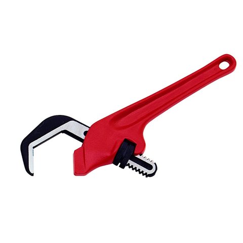
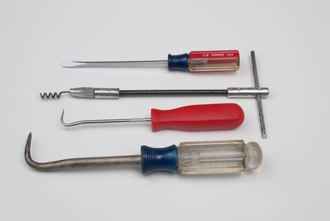
I recently did mine-- I bought this smooth-jawed wrench made by Reed (see pic) which you can buy here http://www.amazon.com/gp/product/B0029P52K2/ref=oh_details_o01_s00_i00?ie=UTF8&psc=1 It opens up to 2 5/8 inches-- wide enough for both the set nut and the packing nut. It certainly made the job a lot easier than those horrible sink drain wrenches that came with my boat-- I've attached a pic of one of these monstrosities.
When you back the nut off, water will come in, but not like Niagara Falls. However it's a good idea to make sure your bilge pump and float switch are in good order. I just left mine in automatic mode-- a week before I had just put in a brand new float switch (I recommend the heavier duty Rule 5 yr. switch instead that little one that comes in the protective cage).
As far as the packing goes-- I went with the graphite-coated packing which is more expensive than the flax or teflon-coated ones, but I believe it may last longer. I bought a tool at my local marine supplier which has a t-handle connected to a flexible cable with corkscrew-like hook on the end (see pic). If you get one, make sure it fits your size packing-- mine is 3/16".
To cut the packing, wrap it around the prop shaft starting with either end of the packing until it wraps around. Mark it at the point where the wrap around just butts up to the end. Then get in a more comfortable place than standing on your head in the lazarette. Cut where you marked the packing, and use this piece as a template to cut the rest of the packing. After you dig out the old packing (mine had very little to dig out), put the first ring in with the two ends together in the 12 o'clock position. The next one in the 6 o'clock position and the next in the 9 or 3 o'clock position. It's important to keep the gaps staggered. Mine only had enough for one ring by the way.
Hope this helps,
James Self, Niko (91)